Activity/Gogo
Introduction
From the GoGo website [1]...
The GoGo board is a programmable device that is designed for sensor-based and control projects. It is suited for building robots, data loggers, and devices for human-computer interaction. Its functionality is inspired by the MIT Cricket and many other programmable devices such as the the Lego Mindstorms, the IRX board, and Basic Stamps.
The GoGo Activity is a Python version of the "Monitor" program (MS Windows) and builds upon the Br-GoGo project code [2]. Effort is under way to replicate most of the functionality of the original program and extend/improve certain areas. At the moment this XO version should be considered "Sugar-coated" rather than "Sugar-ized". The integrated nature of the program means breaking it down into distinct activities would detract from fluid navigation. However there are certain elements which could benefit from Sugar's Sharing and Journalling features and these will be addressed in time.
Please see the sites listed under "Further Information" for GoGo-Board help and documentation. The main purpose of this Wiki page is to help you get started, familiarise you with the use of the GoGo-Board on the XO, specifically with the GoGo Activity and any issues you may encounter. Several other websites are listed at the end of this page, such as the SugarLab "Bugs" page which is where problems and feature requests should be submitted.
Work continues on the GoGo Activity so please check back soon for news of new features.
Quick Tour
Install & Launch
Installation is performed on the XO clicking the "download" button on the GoGo Activity Web Page [3]. The activity can be identified by the ingeniously imaginative icon shown below. This icon should be on your home-screen straight after installation. If not then check for it in the "list-view" mode of the home-screen and click the star on the left to have the icon displayed on the Favorites-view. If GoGo is no where to be found then some older XO/OS's require that Sugar be restarted using ctrl-alt-erase.
NOTE: POWER-SAVING IS DISABLED WHILE GOGO IS RUNNING!!! The GoGo-Board is a USB-connected device and, unless you use batteries, loses power and disconnects when the XO enters power-saving mode. This can be inconvenient so power-saving is temporarily disabled while the activity is running but returned to previous state on exiting. Methods to avoid disabling power-saving or limit it's use are under discussion.


Connection Tab: Plug In, Switch On & Connect!
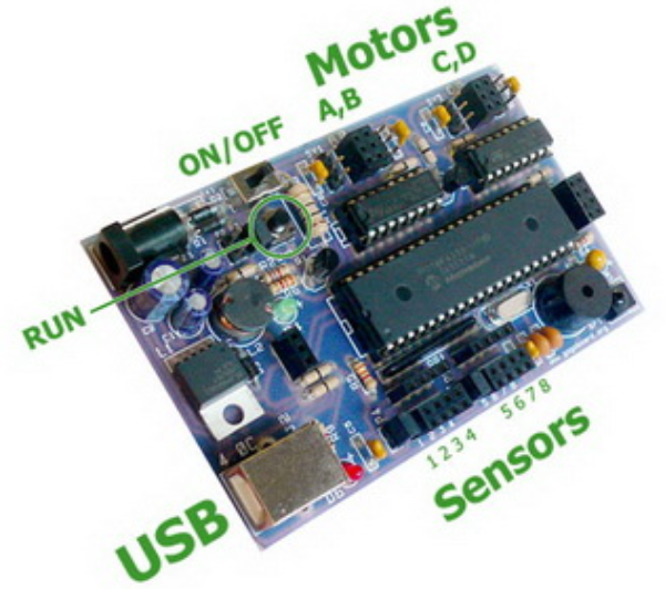
The following image provides an overview of the GoGo-Board itself. Take particular note of the On/Off switch, the green LED (left-center), the red LED next to the USB connector, the beeper (round thing on the right) and a programmable LED near it. All of these are useful for diagnosing connection problems, as described below.

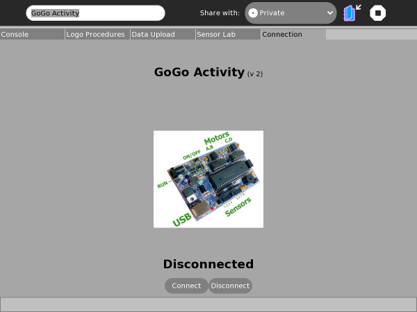
On starting the GoGo activity the Console-Tab is displayed as shown below. In the top of the central region is the name and version of the activity. Please quote the version number if you encounter any problems (Suggestions & Bug Reports). In the center is the image of the GoGo-Board itself, which will be larger is the next version. Below that is the current status "GoGo Connected"/"GoGo Disconnected" followed by "Connect"/"Disconnect" buttons. Also note the status-bar at the bottom of the screen which displays (sometimes transient) messages.

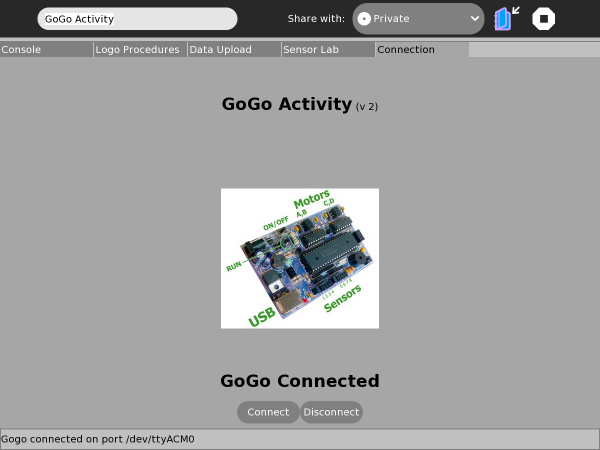
The board should be plugged in switched on before clicking the "Connect" button. When the board is switched on the green LED lights up, the beeper beeps and the programmable LED flashes a couple of times. When clicking the "Connect" button watch out for the red LED near the USB connector, which should flash when the XO and GoGo-Board communicate. If the red LED does not flash then the GoGo activity will have failed to connect and you should consult the "Failing To Connect" section on this page. All being well the connection status should show "GoGo Connected" along with the port being used in the status-bar, as shown below:

Console Tab: Control & Monitor
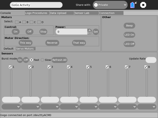
The Console Tab allows you to directly control motors & servo's, the programmable LED, the beeper and to monitor GoGo connected sensors. In the image below the upper left section is for controlling motors and servo's. Note that this is a tabbed-section (with the tabs at the bottom) for selecting between Motors/Servo's. Also note that only those selected in the group of check-boxes denoted A/B/C/D will be effected. The lower section allows one-shot or continuous sensor monitoring and each sensor "type" can be selected from the drop-down boxes at the bottom. The available sensors-types is dictated by those listed in the "Sensor-Lab" tab, detailed later.

Logo Procedures Tab: On-board Programs
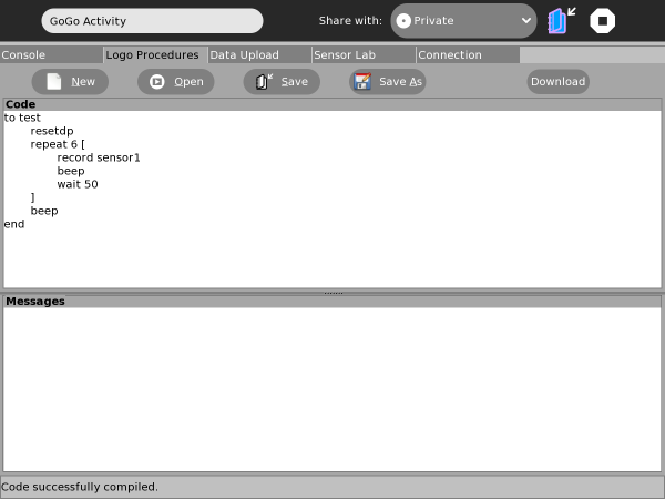
The GoGo-Board can store compiled Logo code which can be run by clicking the board's "run" button. Stored code can be run with/ without the board being connected to the XO (batteries or alternative power source are required when the board is untethered). Code is created, edited, saved, loaded and "downloaded" via the Logo Procedures tab shown in the image below. Code is compiled and uploaded (if no errors) in a single step when the "Download" button is clicked. The "Messages" section will report any errors in the Logo code, in which case nothing will actually be downloaded to the board.
Data Upload Tab: Capture, Graph & Save
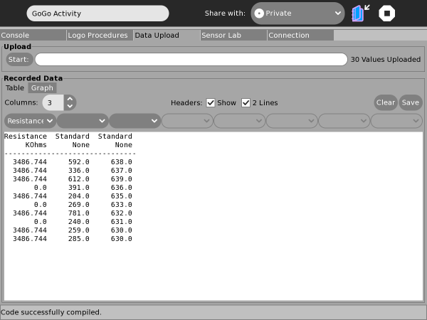
Logo procedures can include commands to capture data and store it on-board until uploaded to the XO. This can be done on the "Data Upload" tab (shown below) by clicking on the "Start" button (top left). The adjacent progress-bar and upload-count will update as data is uploaded. The data will be displayed in the "Recorded Data" section after the upload completes. Data can be displayed in Table or Graph format. In Table format the data can be formatted across a number of columns, which is required when data from more than one sensor/ source is interleaved. A sensor "type" can be selected to display the name & units and to apply calibration to each column (see next section for how this information is created). Sensor Names & Units are used to display column headers. Name and Unit can be on the same line ("Name (Units)") or split on their own line (a two-line header). Data can be saved in Comma-Separated-Variables (CSV) format along with one/two lines of header (if "Headers" check-box is selected).

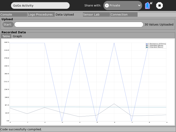
The "Graph" tab provides a graphical view of the data with each column of data plotted individually in overlay:

Sensor-Lab Tab: Calibration Data
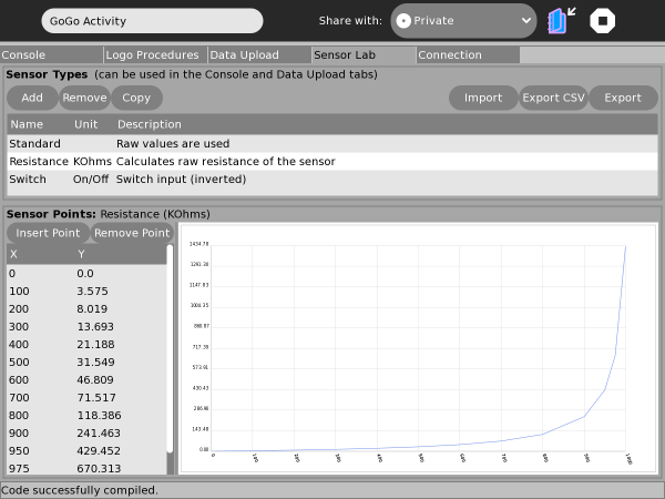
Sensor values, even for switches, fall in the range 0..1023. The Sensor-Lab is where particular sensor "types" can be created to calibrate these values, give more meaningful names and specify the units used (eg, Resistance, KOhms). Calibration data is defined by specifying a number of calibration "points" between which the application will interpolate to convert the raw sensor values. In this way a library can be created of commonly encountered sensor types and their calibration data can be assigned when monitoring sensors in the Console tab and when importing captured data in the "Data Upload" tab. In the image below you can see the list of sensors, the calibration points for the selected sensor and a (slightly rough) idea of the shape of the calibration curve in the graph. For easier creation and editing of calibration data the information for each sensor can be exported and imported in both Comma-Separated-Variables (CSV) format or a custom "Sensor" format.

Problems
Failing To Connect
After checking the board is turned on, if connection fails on clicking "Connect" then try it a few more times. For reasons unknown at the moment it may take two or three attempts before connection succeeds. Still no luck? Turn off, turn on, try again. Still no luck? Now we need to identify the problem. The board needs to be recognised by the OS and a Linux device file mounted, the device file must be assigned a group in common with the user named "olpc" and the group must have read-write permissions on the device file. Here is how to check using the Terminal activity:
1. Shortly after plugging the device/ turning it on enter the following command:
       [olpc@xo-73-22-91 ~]$ dmesg | tail -n 8
       [22543.590117] usb 3-1: new full speed USB device using uhci_hcd and address 4
       [22543.755225] usb 3-1: New USB device found, idVendor=0461, idProduct=0033
       [22543.755238] usb 3-1: New USB device strings: Mfr=1, Product=2, SerialNumber=0
       [22543.755249] usb 3-1: Product: SERIAL DEMO
       [22543.755257] usb 3-1: Manufacturer: CCS
       [22543.755708] usb 3-1: configuration #1 chosen from 1 choice
       [22543.757578] cdc_acm 3-1:1.0: This device cannot do calls on its own. It is not a modem.
       [22543.757797] cdc_acm 3-1:1.0: ttyACM0: USB ACM device
2. The output above shows the GoGo-Board is assigned the "ttyACM0" device. The permissions of that device can be determined with the following:
       [olpc@xo-73-22-91 ~]$ ls -l /dev/ttyACM0
       crw-rw---- 1 root dialout 166, 0 2011-01-17 18:26 /dev/ttyACM0
3. Above we can see the device is a member of the "dialout" group, which has rw permissions. Now to check what groups user "olpc" is a member of:
       [olpc@xo-73-22-91 ~]$ groups
       olpc wheel uucp dialout video audio
...yep, user "olpc" is a member of "dialout". So in the above example all is well. If your results differ from these then please post a bug (Suggestions & Bug Reports). Note that some older XO/OS's use different device files and/or groups and it may need root access to fix any problem.
Upcoming Changes
Improving existing features is an ongoing effort. These are new feature are currently being worked on:
- Logo commands reference on-screen
- Logo line numbering
- Logo syntax highlighting
- Strip-chart for sensor monitoring
Contributing To Development
The GoGo Activity is an open-source project and contributions in terms of code, graphics, testing and feedback are welcome. Bug reports should be submitted on SugarLab's Bug site (Suggestions & Bug Reports). Code and graphics should be contributed via the GIT repository [5]. Language translations should be via SugarLab's Pootle port-hole [6].
Please also remember that the GoGo Activity is originally based on Br-GoGo [2] and the intention is to eventually contribute back to that project so please also consider contributing to that project.
Suggestions and Bug Reports
When reporting bugs please provide as much information as possible including version numbers for XO hardware, OS and Sugar.
Further Information
[2] [http://br-gogo.sourceforge.net/ Br-GoGo Project Website
[4] SugarLabs Bugs
[6] translations