Difference between revisions of "Activities/Turtle Art/Using Turtle Art Sensors"
Tonyforster (talk | contribs) |
Tonyforster (talk | contribs) |
||
| Line 24: | Line 24: | ||
==Pitch Mode== | ==Pitch Mode== | ||
| − | Pitch Mode is set up for | + | Pitch Mode is set up for the internal microphone but can also be accessed through the microphone jack, 2V DC bias is on, AC coupled, +20dB boost is on. The frequency of the strongest component is reported in Hz. The resolution is +-8Hz |
==Sound Mode== | ==Sound Mode== | ||
Revision as of 00:47, 8 November 2010
CAUTION. APPLYING EXTERNAL POWER SOURCES TO THE XO LAPTOP'S MICROPHONE INPUT CAN CAUSE PERMANENT DAMAGE. BE SURE YOU READ AND UNDERSTAND THE FOLLOWING BEFORE CONNECTING POWER SOURCES TO YOUR LAPTOP. DO NOT CONNECT TO HAZARDOUS VOLTAGES
Specifications
The OLPC XO can measure external inputs with its microphone jack.
Standard 3.5mm 2-pin switched mono microphone jack; selectable 2V DC bias; selectable sensor-input mode (DC or AC coupled); selectable +20dB boost.
If using a stereo plug it is the tip (usually the red wire) plus the earth.
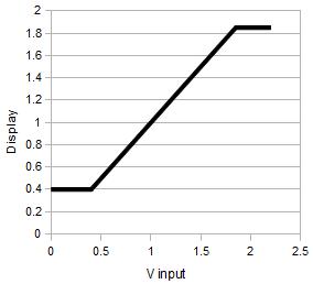
It is protected at the input by a 5V zener diode and has a measurement range of 0.4V to 1.85V. The allowable input is -0.5V to 5V. Inputs outside this range will cause excessive current and damage. Even a single 1.5V battery can cause damage if connected reverse polarity.
Addition of a 150k ohm series resistor would (I expect, no guarantee) give a reduced sensitivity in voltage mode (0-4V) but allow inputs to +- 100V without damage. Input impedance in resistance, volume and pitch modes is much lower but a 1k ohm series resistor should still allow inputs to +-12V.
If applying an external voltage, it is highly recommended that test leads be made up with a microphone plug and an inbuilt series resistor.
Voltage Mode
Measurement range is DC 0.4V to 1.85V. Voltages less than 0.4V report as 0.4V, voltages greater than 1.85V report as 1.85V. Accuracy is around 3% of full scale.
Resistance Mode
Measurement range is 750 ohms to 14k ohms, resistances less than 700 ohms report as 700 ohms, greater than 14k ohms report as 14k ohms. Accuracy is around 5% with respect to the full scale voltage measured across the resistor, this translates to round 50 ohms at bottom scale and 2k ohms at top scale. (A series protection resistor of around 700 ohms would give a measurement range of 0 - 13k ohms and protection against +-8V inputs.)
Pitch Mode
Pitch Mode is set up for the internal microphone but can also be accessed through the microphone jack, 2V DC bias is on, AC coupled, +20dB boost is on. The frequency of the strongest component is reported in Hz. The resolution is +-8Hz
Sound Mode
Raw data ranging -32000 to 32000, set up is for microphone, AC coupled, Bias on, Boost on. Sensitivity is 2uV per unit or 16mV full scale, so sine wave clipping sets in at round 10mV RMS.
Volume Mode
Ranging 0 to 32000, set up is for microphone, AC coupled, Bias on, Boost on. Volume is the rectified average of Sound, ie. volume=average(abs(sound))
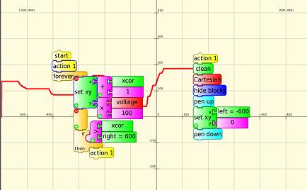
Graphing the output
Source file as doc File:Oscillo.doc
Measuring Temperature
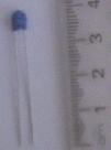
Connect the TDC05C247 thermistor, Specifications:
- NTC (Negative Temperature Coefficient) Thermistor
- Operating temperature range: -20 Celsius ~ +125 Celsius
- Maximum power rating: 500mW
- Nominal resistance at 25 Celsius 4.7k ohms
Teaching ideas:
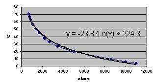
- measure resistance and temperature with a thermometer
- construct your own calibration function
- exponential decay
- diurnal temperature
- heat of reaction, weak acid and base
Measuring Soil Moisture
Two probes into the soil measured in resistance mode. Only a few cm of wire are required to bring soil within the resistance range of 700 ohms to 14k ohms
Measuring Water Salinity
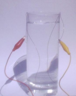
Place two copper wires into a glass of water. Experiment with your water and wire diameter, I was able to get a measurement of 5k ohms with 12cm of wire in tank water.
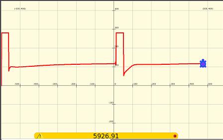
Use the graphing software shown previously but set the turtle y to resistance/50 to scale to the screen size, each 100 on the vertical scale corresponds then to 5000 ohms.
The graph shows first an unconnected circuit (14k ohms) then the circuit is connected. Note how the resistance slowly rises. The terminals are reversed mid screen, the sudden dip and gradual rise are more pronounced. Why is this? Electrolysis products (microscopic bubbles of hydrogen and oxygen for pure water) build up near the electrodes.
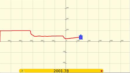
Small amounts of salt are added to tank water, bringing the resistance down from 5k ohms to 2k ohms. Salt added on two occasions
