Difference between revisions of "Activities/Turtle Art/Using Turtle Art Sensors"
Tonyforster (talk | contribs) |
Tonyforster (talk | contribs) |
||
| Line 664: | Line 664: | ||
and join that session on another laptop | and join that session on another laptop | ||
| − | [[File:Mesh.png | | + | [[File:Mesh.png |150px]] |
| + | |||
| + | The following program will transmit the camera output from one laptop to the other. Transmitting large amounts of data will overload the network so the image is displayed 20% size and sent every 2 seconds. | ||
| + | |||
| + | [[File:Image clipping cctv.png]] | ||
| + | |||
| + | |||
| + | ===Remote door bell === | ||
| + | Based on the previous door bell example, this sounds an alarm in one laptop when an electrical connection is made on another. | ||
==Links== | ==Links== | ||
Revision as of 03:54, 16 February 2011
CAUTION. APPLYING EXTERNAL POWER SOURCES TO THE XO LAPTOP'S MICROPHONE INPUT CAN CAUSE PERMANENT DAMAGE. BE SURE YOU READ AND UNDERSTAND THE FOLLOWING BEFORE CONNECTING POWER SOURCES TO YOUR LAPTOP. DO NOT CONNECT TO HAZARDOUS VOLTAGES
Specifications
The OLPC XO can measure external inputs with its microphone jack.
Standard 3.5mm 2-pin switched mono microphone jack; selectable 2V DC bias; selectable sensor-input mode (DC or AC coupled); selectable +20dB boost.
If using a stereo plug it is the tip (usually the red wire) plus the earth.
The XO1 is protected at the input by a 5V zener diode. The allowable input is -0.5V to 5V. Inputs outside this range will cause excessive current and damage. Even a single 1.5V battery can cause damage if connected reverse polarity.
The XO1.5 is protected by a resistor,(1/16W 470 ohm SMD0402) and a pair of diodes to ground and to +3.3V which should protect -6V to +9V continuously, and up to higher voltages for shorter periods of time. Similar protection is planned for the XO1.75.
For the XO1, the addition of a 150k ohm series resistor would (I expect, no guarantee) give a reduced sensitivity in voltage mode (0-4V) but allow inputs to +- 100V without damage. Input impedance in resistance, volume and pitch modes is much lower but a 1k ohm series resistor should still allow inputs to +-12V.
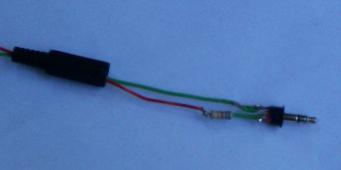
If applying an external voltage to the XO1, it is highly recommended that test leads be made up with a microphone plug and an inbuilt series resistor.
680 ohm series resistor on a 3.5mm audio plug
Test leads with a zener diode and series resistor would expand the safe range for the XO1.5 and XO1.75.
Damage can also be caused by applying voltages between the grounds of any of the external sockets.
Voltage Mode
XO1
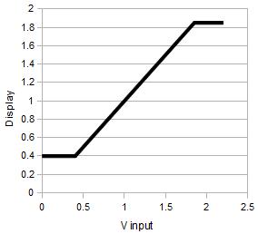
Measurement range is DC 0.4V to 1.85V. Voltages less than 0.4V report as 0.4V, voltages greater than 1.85V report as 1.85V. Accuracy is around 3% of full scale. Impedance 140k ohms to a 0.6V bias.
XO1.5
0.17V - 3.0V, impedance 15k ohms to a 1.7V bias. (Still buggy, click stop to clear bug.)
Resistance Mode
XO1
Measurement range is 750 ohms to 14k ohms, resistances less than 700 ohms report as 700 ohms, greater than 14k ohms report as 14k ohms. Accuracy is around 5% with respect to the full scale voltage measured across the resistor, this translates to round 50 ohms at bottom scale and 2k ohms at top scale. (A series protection resistor of around 700 ohms would give a measurement range of 0 - 13k ohms and protection against +-8V inputs.)
XO1.5
2k ohms to open circuit. (Still buggy, click stop to clear bug.)
Pitch Mode
Pitch Mode is set up for the internal microphone but can also be accessed through the microphone jack, 2V DC bias is on, AC coupled, +20dB boost is on. The frequency of the strongest component is reported in Hz. The resolution is +-8Hz
A guitar tuner
Resolution is +-8Hz,
resolution = RATE/(max_samples * 4)
where:
RATE = 48000   file audiograb.py
self.max_samples = 1500  file talogo.py
4 for i in range(4) in _get_pitch in talogo.py
These settings could be edited see Activity_Team/Modifying_an_Activity
Sound Mode
Raw data ranging +-32000 XO1, +-10,000 XO1.5. Set up is AC coupled, Bias on, Boost on. Sensitivity is 2uV per unit or 16mV full scale, so sine wave clipping sets in at round 10mV RMS on the XO1. For the XO1.5, sensitivity is approximately 8uV per unit.
With the inbuilt microphone, normal speech is approximately +-1000 XO1 and +-200 XO1.5.
Volume Mode
Ranging 0 to 32000 XO1, 0 to 10,000 XO1.5, set up is for microphone, AC coupled, Bias on, Boost on. Volume is the rectified average of Sound, ie. volume=average(abs(sound))
Idea: you could graph the 24 hour sound level in a school corridor or beside a busy road.
Graphing the output
Source file as doc File:Oscillo.doc
Measuring Temperature
(For instructions on using the LM35 sensor, see http://wiki.laptop.org/go/Making_XO_sensors/Making_a_Temperature_Sensor and http://www.reducativa.com/xo/man-sis-sensoresdetemperatura.pdf - in Spanish)
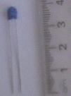
Connect the TDC05C247 thermistor, Specifications:
- NTC (Negative Temperature Coefficient) Thermistor
- Operating temperature range: -20 Celsius ~ +125 Celsius
- Maximum power rating: 500mW
- Nominal resistance at 25 Celsius 4.7k ohms
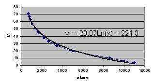
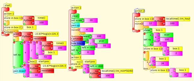
Left, the resistance was plotted against temperature and the curve of best fit calculated. Right the blocks convert from resistance to temperature C.
Teaching ideas:
- measure resistance and temperature with a thermometer
- construct your own calibration function
- exponential decay
- diurnal temperature
- heat of reaction, weak acid and base
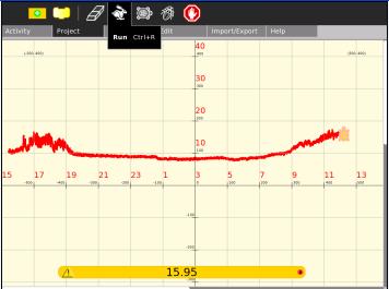
24 hours temperature
The following Turtle Art project captures and graphs 24 hours temperature. You may need to set your time zone and disable power management in 'My Settings'.
File:Oscillo daily temp.doc ta project as doc (rename to .ta outside of Sugar or copy contents to a ta project)
Measuring Soil Moisture
Two probes into the soil measured in resistance mode. Only a few cm of wire are required to bring soil within the resistance range of the XO1, 700 ohms to 14k ohms (XO1.5, 2k ohms to open circuit).
Measuring Water Salinity
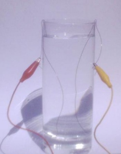
Place two copper wires into a glass of water. Experiment with your water and wire diameter, I was able to get a measurement of 5k ohms with 12cm of wire in tank water.
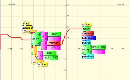
Use the graphing software shown previously but set the turtle y to resistance/50 to scale to the screen size, each 100 on the vertical scale corresponds then to 5000 ohms.
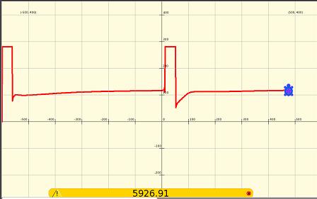
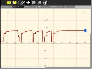
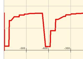
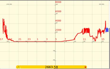
The graph shows first an unconnected circuit (14k ohms) then the circuit is connected. Note how the resistance slowly rises. The terminals are reversed mid screen, the sudden dip and gradual rise are more pronounced. Why is this? Electrolysis products (microscopic bubbles of hydrogen and oxygen for pure water) build up near the electrodes.
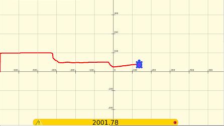
Small amounts of salt are added to tank water, bringing the resistance down from 5k ohms to 2k ohms. Salt added on two occasions
Generating Electricity from a Changing Magnetic Field
Requires a refrigerator magnet, often given away free with advertising on it.
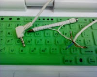
Wrap 50 turns of insulated wire onto a nail and connect the two ends to a phono plug as shown (if it is a stereo plug, probably the red wire and the copper shield). Connect the phono plug to the microphone input. Graph the Sound or Volume block. This is better with the XO1 than the XO1.5 because it is more sensitive.
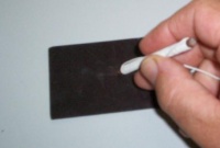
- Wipe the sharp end rapidly over the back of the fridge magnet, try both directions.
- Try a different number of turns of wire
- Try moving the nail more slowly, what happens?
- What is happening?
- Why does it work better on one axis of the magnet? (hint rub 2 magnets together)
- Graph pitch. Explain the result.
Carbon Microphone
Required:
- charcoal
- aluminium foil
- plastic lid
- wire
- rubber band
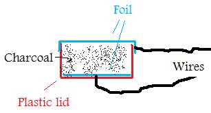
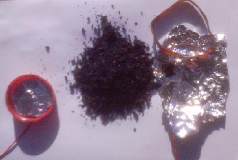
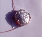
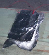
Crush the charcoal to a fine powder. Make a hole in the centre of the lid. Strip a small amount of insulation from the wire, pass the wire through the hole. Then place a piece of foil against the wire. Fill the lid with crushed charcoal. Place foil over the charcoal and secure with a rubber band. Connect a wire to this foil. Try to get the foil under tension.
Experiment with the fineness of the crushed charcoal and the tension in the foil. The more squashed the charcoal is, the lower the resistance. With the XO1, aim for a resistance of around 3k ohms and for the XO1, definitely 700 ohms < resistance < 14k ohms. (XO1.5 2kohms<resistance<open circuit).
Graph the resistance, pressing on the foil changes the resistance. You have built a pressure sensor. It can also sense air pressure. You have built a microphone. Change to Sound sensing. On my first try I was able to sense clapping.
Lemon battery
See http://en.wikipedia.org/wiki/Lemon_battery
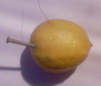
With a copper wire and galvanised nail, the measured voltage is 0.93V, comfortably within the measurement range of the XO1 laptop. The laptop produced negligible loading on the open circuit voltage on the XO1. With copper wire and an ungalvanised nail the voltage was 0.49V.
The internal resistance of the lemon battery is around 10k ohms, the input impedance of the XO1.5 of 15k ohms introduces considerable error.
Experiment with different materials. Try lemon cells in series.
Door bell / Burglar alarm
Visitors touch the two wires together to ring your door bell. Alternatively, arrange two wires to touch as your door opens.
Here are the Turtle blocks:
The Python Code Block ![]() is used to sound an alarm in your loudspeakers.
is used to sound an alarm in your loudspeakers.
You need to type the following into Pippy and save to the Journal. Type it exactly as shown, the indents on the last 3 lines are important, for the characters '-l 1' the first is an 'el' and the second a 'one'.
Then in Turtle Art, load the Pippy code ![]() into the Python Code Block
into the Python Code Block ![]() , then run your program.
, then run your program.
Two-tone alarm
Use the following Turtle blocks and Pippy code for a warbling alarm
How it works: the 1000 and 1100 blocks are input x in the Python code. The -f option in speaker-test is the frequency, {0} gets replaced by x which in turn is replaced by 1000 or 1100 so speaker-test is sent either -f 1000 or -f 1100 giving frequencies of 1000 Hz or 1100 Hz.
Measuring AC Amps
An inexpensive current transformer can be built to measure AC amps.
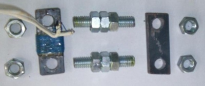
50 turns of insulated copper wire are wrapped on a soft iron bar. Threaded shaft, nuts and another bar complete the magnetic circuit.
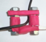
Assembled, with optional red heat shrink. The current in the black wire is measured. The 50 turns of fine wire connect to the XO1 in Volume Mode. The maximum is about 15 amps AC before clipping of the AC waveform occurs.
To change sensitivity, vary the number of turns.
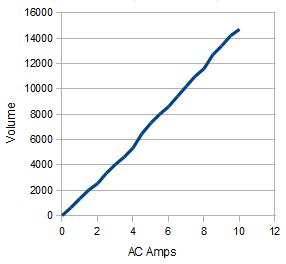
Volume measured on XO1, 50 turns of wire.
Measuring power
DO NOT CONNECT TO MAINS POWER. DO NOT WORK NEAR EXPOSED ELECTRICAL CONNECTIONS.
Power = AC Volts x AC Amps x Power Factor
In mains circuits, the voltage is usually known. Typically, power factor is 0.8 or 1.0 depending on the electrical load.
Measuring DC Amps
DO NOT CONNECT TO DANGEROUS VOLTAGES. THE LAPTOPS CAN BE DAMAGED BY EXCESS OR REVERSE VOLTAGE ON EITHER THE MICROPHONE SOCKET OR POWER SOCKET AND BY EXCESSIVE CURRENTS BETWEEN THE GROUNDS OF ANY OF THESE SOCKETS
See also Activities/TurtleArt/Using_Turtle_Art_Sensors#Measuring_DC_amps_2
The current flowing in a DC circuit can be measured by measuring the voltage accross a series resistor. The resistor value is chosen so that the voltage across it is within the measurement range of the XO (0.4-1.8V XO1, 0.17V-3.0V XO1.5) and as low as possible consistent with that to minimise influences on the measured circuit.
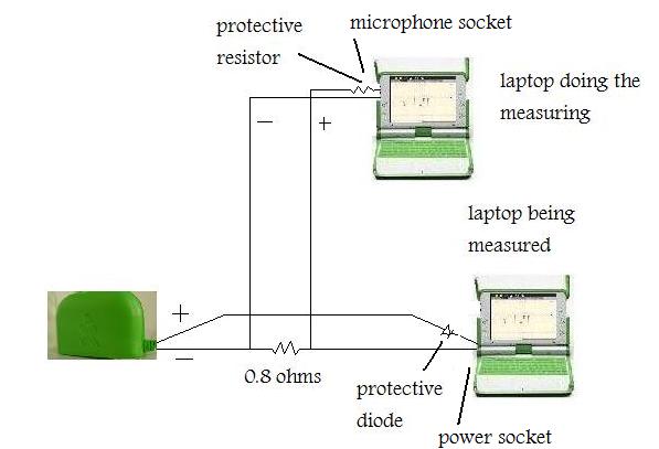
Shown below, a XO1.5 is measuring the DC charging current of a XO1.0. The voltage is measured across a 0.8 ohm series resistor. The phono plug of one laptop has an inbuilt 680 ohm series resistor to protect against excessive voltage. (Though the power plug of the other laptop had an inbuilt series diode to protect against reverse voltage, later information shows this was not necessary as the XO power input has an absolute maximum rating of -30V to +40V).
This circuit cannot be used for one laptop to monitor itself because the grounds must be at 2 different points.
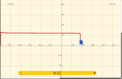
The laptop was charged from a fully discharged state while turned off. The voltage delivered to the laptop was only (11.46 -0.7)V because of losses across the current measuring resistor and the protection diode. The plot has a scale of 0.5V/square /0.8 ohms = 0.625 amps/square and 1200 seconds/square or 20 minutes per square. The full charge took 156 minutes at 0.775 amps. The minimum voltage the XO1.5 can measure is 0.17V corresponding to 0.21 amps.
Turtle Art project as doc File:Oscillo current.doc
Importing Logged Data into other Activities
Saving logged data to the clipboard
Logged data can be pushed onto the heap, then when logging is finished, the contents of the heap can be placed onto the clipboard for use in other Activities.
Copy the following code into Pippy (from V104 this is included with the samples)
def myblock(lc, x):
    from gtk import Clipboard
    from tautils import data_to_string
    Clipboard().set_text(data_to_string(lc.heap))
    return
Save to the journal, then in Turtle Art, load the Pippy code ![]() into the Python Code Block
into the Python Code Block ![]() . When the Python Code Block is executed, the contents of the heap are placed on the clipboard.
. When the Python Code Block is executed, the contents of the heap are placed on the clipboard.
Example, import temperatures into Gnumeric spreadsheet
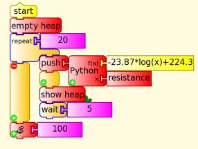
For example, temperatures are logged and then copied to the clipboard. This builds on measuring with a thermistor and the XO1 previously. First load the Pippy code ![]() . The temperature is measured and pushed to the heap, then a 5 second delay. This repeats 20 times. Then the contents of the heap are copied to the clipboard.
. The temperature is measured and pushed to the heap, then a 5 second delay. This repeats 20 times. Then the contents of the heap are copied to the clipboard.
TurtleArt can be run in Gnome on the XO. The data is then pasted to a Gnumeric spreadsheet. The data is converted text to columns (the Data menu), the leading '[' and trailing ']' are manually deleted, the data is graphed. (Unfortunately, on the XO, the Data, text to columns dialog boxes are off screen, alt f alt f shift tab shift tab shift tab allow conversion of comma separated data.)
Temperature data imported into Gnumeric spreadsheet
Saving logged data to the Journal
The following code File:Saveheaptojournal.doc (from V104 this is included with the samples) in the Python Code Block will save the heap as a text file named 'heap' in the Journal. The file 'heap' can then be opened with Write or Edit.
def myblock(lc, x):
    from tautils import get_path, data_to_file
    from sugar.activity import activity
    from gettext import gettext as _
    import os.path
    from sugar.datastore import datastore
    from sugar import profile
    # Save the heap to a file (JSON-encoded)
    heap_file = os.path.join(get_path(activity, 'instance'), 'heap.txt')
    data_to_file(lc.heap, heap_file)
    # Create a datastore object
    dsobject = datastore.create()
    # Write any metadata (specifically set the title of the file
    #                     and specify that this is a plain text file).
    dsobject.metadata['title'] = _('heap')
    dsobject.metadata['icon-color'] = profile.get_color().to_string()
    dsobject.metadata['mime_type'] = 'text/plain'
    dsobject.set_file_path(heap_file)
    datastore.write(dsobject)
    dsobject.destroy()
    return
Logging at regular intervals
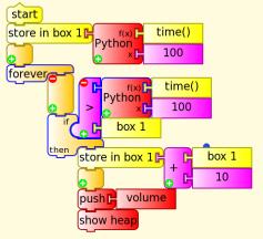
The following takes readings at regular intervals, in this case 10 seconds and pushes the result to the heap. For example, use for daily temperature, light, power, noise. Taking readings hourly, quarter hourly etc.
Acceleration on an inclined plane
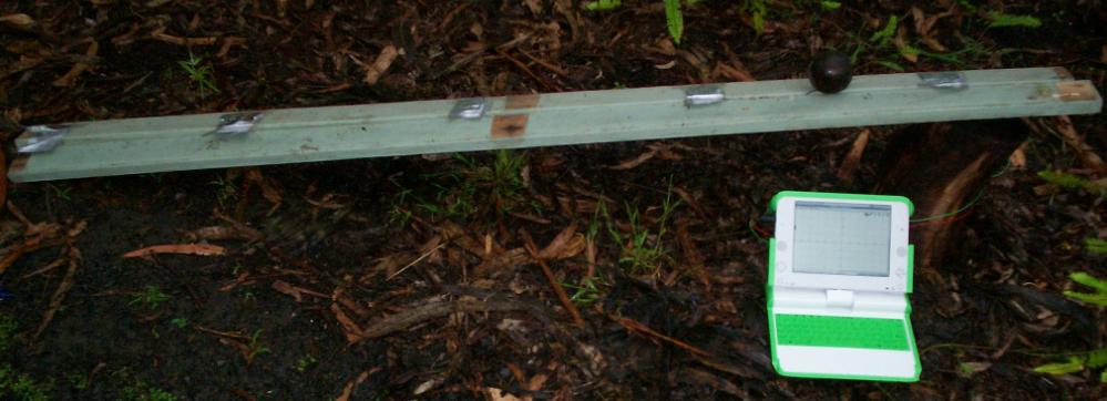
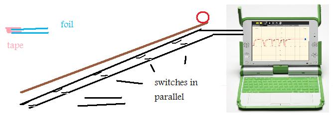
The XO laptop can be used to do experiments on motion, rolling a ball down a ramp. The XO1.5 is faster and better suited for this. Inexpensive sensor switches can be made of aluminium foil. The switches are 5cm wide to provide an 'on' time which is long enough to measure.
The logging rate can be increased (Turtle Blocks104) by patching one of the Turtle Art files, talogo.py in directory home/olpc/Activities/TurtleArt.activity/TurtleArt changing self.max_samples from 1500 to 150, This reduces the repeat loop from 12mS to 4mS but there is around 50mS jitter. Datalogging can be done without patching the file, using wide switches and shallow ramps keeps the events within the capability of the XO laptop.
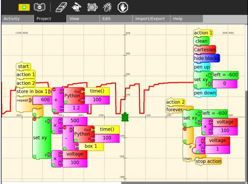
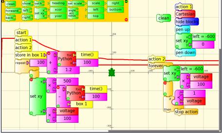
Shown below is a triggerable oscilloscope with calibrated timebase. Action 1 clears the screen and draws the scale, the program waits in action 2 until triggered by the first switch. The graphing then starts, time() in seconds is multiplied by 500 to set the horizontal position so 500 screen units or 5 squares equals one second.
File:Singleshottriggerableoscilloscope.doc TurtleArt project as doc
Switches were placed at 20cm, 60cm, 100cm, 140cm, and 180cm along a ramp of length 180cm and height 25cm.
The oscilloscope data is shown below, each square is approximately 200mS
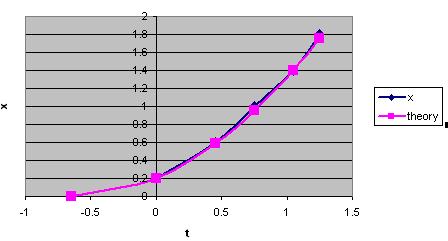
The match between theory and experiment is shown below. Note, the mathematics for a rolling ball is not simple, the potential energy is converted into translational kinetic energy, Kt and rotational kinetic energy, Kr.
Mgh = Kt + Kr = 1/2 Mv^2 + 1/2 Iw^2
For a solid sphere, Kt/Kr =5/2 (see Work and energy in rolling motion or Wikipedia)
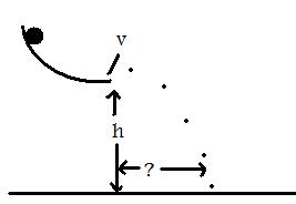
A simpler experiment is to accelerate a ball down a curved ramp, measure the horizontal exit velocity with two switches and predict the landing position as shown below. The ramp is preferably curved so that the ball is not bouncing when it hits the switches.
h = 1/2 g t^2
t=sqrt(2h/g)
horizontal distance = vt = v x sqrt(2h/g)
In this case, switch spacing is 0.5m, h=0.6m, time 1.9 squares @200mS per square, g=9.8 and the horizontal distance was 0.4m
distance = v x sqrt(2h/g)
= 0.5/0.38 x sqrt (2x 0.6/9.8)
= 0.46m  (measured 0.4m)
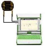
Light dependant resistor (LDR)
The ORP12 is a 'classic' cadmium sulphide photocell. Tests were done on a LDR that is 'similar to Philips ORP12'
http://www.jaycar.com.au/productView.asp?ID=RD3480
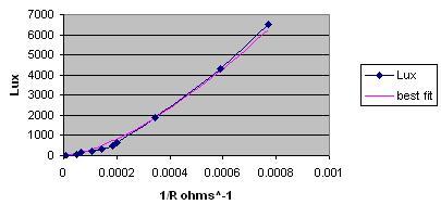
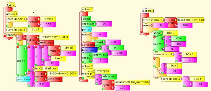
For this cell, the calibration was Lux = 3 * 10^8 * (R^ -1.5034)
For the XO1 (700 ohms -14k ohms) the range is 170 Lux to 15000 Lux (brighter home artificial light to outdoor overcast).
For the XO1.5 (2k ohms - open circuit) the range is 2 Lux to 4000 Lux (dim home artificial lighting to indoor daylight).
The project below graphs the light level in Lux over a 24 hour period.
Turtle Art project as doc File:Turtle Art lux.doc
Photovoltaic panel
IT IS RECOMMENDED THAT A SERIES PROTECTION RESISTOR BE BUILT INTO THE PHONO PLUG AND LEADS IF USING AN EXTERNAL VOLTAGE
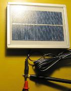
Shown is the solar cell from the D.LIGHT S250 [[1]]
It has a 6V solar cell, the outer connection is -ve and the inner +ve
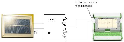
A voltage divider is needed to bring it into the range of the XO1 0.4V to 1.85V (XO1.5 0.17 to 3.0V). With the values shown below, the sensitivity is reduced by
1k/(1k +2.7k) = 1/3.7
giving a maximum of 6.8V XO1 or 11.1V XO1.5
RC time constant
IT IS RECOMMENDED THAT A SERIES PROTECTION RESISTOR BE BUILT INTO THE PHONO PLUG AND LEADS IF USING AN EXTERNAL VOLTAGE
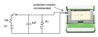
The theoretical time constant for a parallel resistor/capacitor is
T = RC
T in seconds, R in ohms and C in farads
Turtle Art project as doc File:Oscillo with trigger 1rc.doc
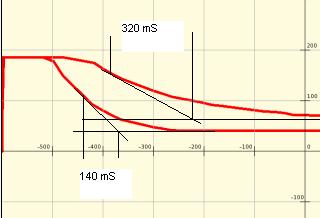
The plot below was drawn by Turtle Art (black lines and annotations were added later). C was 4uF, the load provided by the XO is in the order of 100k ohms. In the two plots, Rx was 100k ohms and open circuit. The calculated resistance of the XO1 is
R = T/C
= 0.32/(4x10^-6) = 80k
and the parallel resistance of 100k and the XO1 is estimated as
R = T/C
= 0.14 /(4x10^-6) = 35k
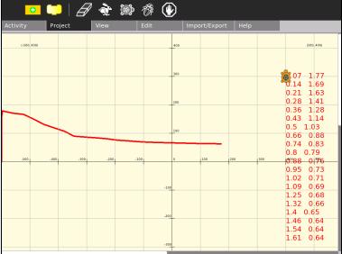
This Turtle Art project File:Turtle Art Activityrcpushstack.doc (as doc, rename from .doc to .ta in Windows or Linux or open as doc and paste into a Turtle Art session) graphs and also writes the time/voltage values to the screen.
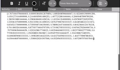
This project will also copy the time/voltage values to the clipboard if the Pippy sample code copy_from_heap.py is copied to the Journal ![]() and then loaded from the Journal into the Python Code Block
and then loaded from the Journal into the Python Code Block ![]() (click on the code block). Shown below, the time/voltage values are pasted into a Write session.
(click on the code block). Shown below, the time/voltage values are pasted into a Write session.
The XO as an audio amplifier
Turtle Art is not required. The following command in Terminal  passes data from the microphone socket to the speaker. You may need to disable power management.
arecord | aplay
You might want to adjust the settings after reading arecord --help and aplay --help
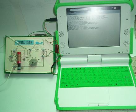
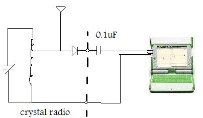
For example, amplify the output of a crystal radio [[2]]
This worked better on the XO1.5, presumably because of its higher processing speed. The headphones are not connected, instead a 0.1uF capacitor is connected between the radio output and the XO input to isolate the detector diode from the XO's DC bias. Theory predicts that a resistor to ground would be necessary at the radio output but practice indicates otherwise.
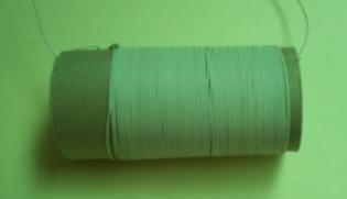
You can construct most of the crystal radio from common materials
The tuned circuit inductor, 75 turns of insulated wire on a toilet paper core.
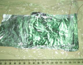
The tuned circuit capacitor, two sheets of aluminium foil approximately 10cm x 10cm sitting loosely and separated by cling wrap gave a resonant frequency of approximately 1MHz with the above inductor.
The 0.1uF capacitor can be made in the same way, the tuning capacitor is estimated at 100pF (10^-10 F) when sitting loose. The coupling capacitor needed is of the order of 0.1uF (10^-7 F). Tightly rolling the layers reduces the plate separation and a workable coupling capacitor was made by tightly rolling only 10cm x 10cm plates.
The diode is still required. The original cat's whisker diode was made with galena crystals. [[3]] Other materials are iron pyrite ("fool's gold", iron disulfide), silicon, molybdenite (MoS2), and silicon carbide (carborundum, SiC). It is also possible to use a rusty razor blade (iron oxide).
FSK Teletype
Send text from one XO to another, encoded as sound waves
The Python Code Block ![]() is used to sound a tone in the loudspeaker, the pitch identifies the key pressed.
is used to sound a tone in the loudspeaker, the pitch identifies the key pressed.
You need to type the following into Pippy and save to the Journal. Type it exactly as shown, the indents on the last 3 lines are important, for the characters '-l 1' the first is an 'el' and the second a 'one'. Click on the Python block to load the code.
The sender
The receiver
Additional challenges
- display a line of received text
- get rid of error - chr() arg not in range (256) produced by high pitch sounds
- use a key such as esc or enter to clear the line
- encode as serial binary data
- add a checksum
- two way communication
- encryption
Capturing with the camera
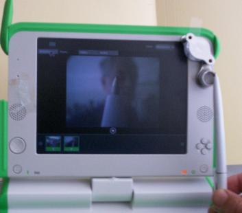
As of version 106 there are blocks to capture an image from the camera, the average brightness and the average rgb colours pushed to the heap
The camera could be used for time lapse photography, motion sensing, light level measuring, colour sensing and more.
Wildlife Photography
Stretch a fine wire across an animal trail so that it breaks or disconnects when an animal uses the track. Connect the two ends to the microphone socket. The following code takes a single photograph. You can modify the code to take a sequence of photos or to retrigger when a second animal passes.
Photographs could be triggered similarly on voltage, frequency, volume, colour or brightness.
Microscope
see http://wiki.laptop.org/go/Microscope for more on using the XO as a microscope.
Placing a maginfying lens in front of the camera lens allows close up photographs to be made. The shorter the focal length, the higher the maginfication.
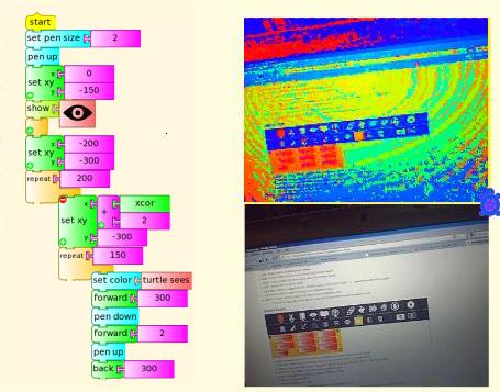
Left, close up of ball point pen, right, an XO takes a closeup of another XO screen
Timelapse Photography
Taking a photo every 600 seconds or 10 minutes
File:Turtle Art Activity timelapse.doc TurtleArt project as doc
More
As of TurtleBlocksV106, the following 2 sections have been partly superceded. The Show Camera blocks ![]() now have the function of the Python code and Show Media blocks
now have the function of the Python code and Show Media blocks  described below.
Load the following code into the Python block ![]()
def myblock(lc, x):
   import gst, time
# grab a frame from camera to file
   pipeline = gst.parse_launch('v4l2src ! ffmpegcolorspace ! jpegenc ! filesink location=/tmp/turtlepic.jpg')
   pipeline.set_state(gst.STATE_PLAYING)
# pause for a second to allow the camera frame to be grabbed
   time.sleep(1)
# stop the camera frame grabbing
   pipeline.set_state(gst.STATE_NULL)
This saves a photo to /tmp/turtlepic.jpg
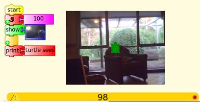
Here is the Turtle Art program as a doc file File:Camera ta.doc. The Show Media block is coded to point to the file /tmp/turtlepic.jpg
["journal", "/tmp/turtlepic.jpg"]
The Turtle Sees block then allows pixels in the image to be read.
There are two ways to make the show media tile point to the file system and not the Journal
1 hand edit the code in the *.ta file with the Write Activity
2 Run Turtle Art under Gnome which has a file choser rather than a Journal object choser, the settings in the block are retained if the saved project is later run under Sugar
Colour effects
Here is an example where you can take a photo and apply colour effects. (Note, 'pen color' is not the same as 'turtle sees'; if you want the actual RGB value of a pixel, use the 'read pixel' block. There is also sample Python code available for setting the RGB value of a pixel.)
File:Camera proc.doc ta project as doc
Hall Effect Sensor
A Hall Effect sensor such as the (Allegro) UGN3503UA Hall Effect Sensor http://www.jaycar.com.au/products_uploaded/ZD1902.pdf can be used to measure magnetic fields. (The Allegro1302 http://www.alldatasheet.com/datasheet-pdf/pdf/120806/ALLEGRO/A1302EUA.html is an alternative to the Allegro3503).
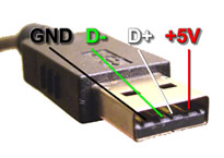
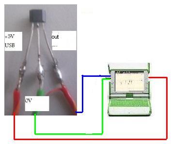
The sensor requires +5V, this is available from the XO's USB connectors.
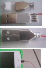
(image http://www.homebrewusb.com)
see also http://wiki.laptop.org/go/Making_XO_sensors/How_to_connect_sensors
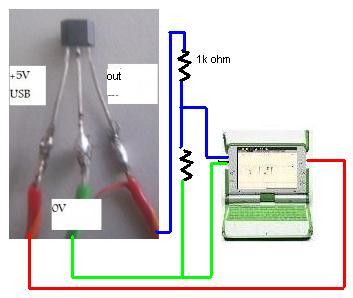
The sensor has an output of half supply voltage (2.5V) at zero magnetic field with a sensitivity of 1.3mV/Gauss. This makes it suitable for connection to the XO1.5 (input range 0.17 - 3.3V). For the XO1.0 (input range 0.4 - 1.85V ) a 2:1 voltage divider is necessary.
left XO1.5 connection, right XO1.0 with 2:1 voltage divider
Compare the sensitivity, 1.3mV/Gauss with common magnetic fields http://en.wikipedia.org/wiki/Gauss_%28unit%29
- 0.31–0.58 gauss: the Earth's magnetic field on its surface
- 50 gauss: a typical refrigerator magnet
- 100 gauss: a small iron magnet
- 2000 gauss: a small neodymium-iron-boron (NIB) magnet
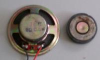
Loudspeakers contain powerful ferrite magnets. The PC speaker magnet (pictured, complete left, disassembled right) produces a voltage swing of +-1V
Yes, the sensor is just sensitive enough to use as a compass, the difference between facing north and south is about 1mV. Try the following blocks:
forever print voltage x 1000
The maximum reading is not on the horizontal, except on the equator. The closer you are to the pole, the further you need to tilt. Why? Why do compass needles still point level?
Bicycle trip computer
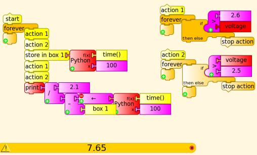
The magnet is mounted on the wheel and the Hall effect sensor senses its magnetic field once a revolution. The program waits in action1 until the magnet arrives, and a voltage of >2.6V is sensed, it then waits in action2 till the magnet has passed, <2.5V. The current time in seconds is stored in box1. The program then waits for the magnet to arrive and pass again. The wheel circumference, 2.1m is divided by the elapsed time (current time-box1) and the result is printed.
Reliable operation is dependant on the alignment of the magnet and sensor and the upper and lower voltage setpoints. The program will operate faster if the blocks are hidden. What is the maximum speed that can be reliably measured? What happens to the display at faster speeds?
File:Turtle Art Activity tripcomputer.doc project as doc
Challenges
- large full screen display
- average speed
- total distance
- maximum speed
- clock and stopwatch
Ampere's Law
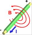
Unlike the current transformer (previously) which can only sense AC amps, the Hall Effect sensor can also sense DC amps. It does this by measuring the magnetic field that a current creates.
![]() http://en.wikipedia.org/wiki/Amp%C3%A8re%27s_circuital_law
http://en.wikipedia.org/wiki/Amp%C3%A8re%27s_circuital_law
- μ0 = 4π×10^−7 N·A−2
- B in tesla (1 gauss = 10^-4 tesla)
- l in metres
- I in amps
In the special case of a wire in free space, the integral is easy to evaluate. At a radius r, the field is uniform over a circular path round the wire , the path length is 2πr. So for the magnetic field B at a radius r from a wire in free space, ![]()
This can be experimentally verified. At a radius of 2.5mm from a wire carrying 1.5 amps , the field is (4π10^-7x1.5)/(2πx2.5x10^-3) = 1.2x10^-4 tesla or 1.2 gauss, at 1.3mV/gauss, the expected voltage is 1.56mV and the measured approximately 1.5 mV.
Measuring DC amps
Though useful for testing Amperes law, the above is too insensitive for most current measurement.
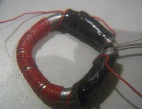
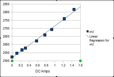
To increase sensitivity, 50 turns of wire were wound on a 100mm nail, bent to a C shape with the Hall sensor in the gap. The mV from the Hall sensor are graphed against the current through the wire in amps.
See also Activities/TurtleArt/Using_Turtle_Art_Sensors#Measuring_DC_Amps
Telemetry
Turtle Art can share 'show text', 'show images', turtle position and fill. This means that sensor data can be transmitted to another XO laptop
Closed circuit TV
Open a Turtle Art session for sharing on one laptop
and join that session on another laptop
The following program will transmit the camera output from one laptop to the other. Transmitting large amounts of data will overload the network so the image is displayed 20% size and sent every 2 seconds.
Remote door bell
Based on the previous door bell example, this sounds an alarm in one laptop when an electrical connection is made on another.
Links
- http://wiki.laptop.org/go/Hardware_specification
- http://wiki.laptop.org/go/Talk:Measure
- http://wiki.laptop.org/go/Measure/Hardware
- http://bugs.sugarlabs.org/attachment/ticket/552/sensor%20gain.xls
- http://wiki.laptop.org/go/Making_XO_sensors
- http://lists.laptop.org/pipermail/devel/2010-November/date.html
- http://wiki.laptop.org/go/File:Ext_audio_1.5.png
- http://sites.google.com/site/solymar1fisica/fisica-con-xo-investigacion- (in Spanish)

